Categories: Featured Articles » Electrician at home
Number of views: 51295
Comments on the article: 1
How to connect an electric sauna stove
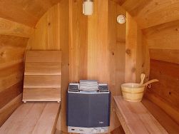
 Sauna is, first of all, a bath. And the creation and maintenance of the necessary microclimate in the bathhouse is a very technologically challenging task. Therefore, it is clear that the bath furnace plays a major role in this process.
And it is not surprising that today sauna furnaces have long been automated and electrified. The microclimate in the sauna is at the mercy of a technique that never makes mistakes and never forgets anything. A modern sauna stove is, in the vast majority of cases, a factory electrical appliance that incorporates several structural elements and requires competent connection and installation.
The structural elements of an electric sauna stove are:
1) The stove itself with a heater and built-in heating elementsas well as terminals for connection. Optionally, the furnace can include a steam generator as well as a tank designed for automatic or manual filling with water. The electric power of the furnace is selected from an approximate calculation of one kilowatt per cubic meter of sauna space.
2) Remote control oven.
3) Temperature sensor and (optional) humidity sensor.
These structural elements are interconnected by means of wires and / or cables. The circuit diagram is not particularly complicated: the mains voltage is supplied to the input power terminals of the control panel, and a line supplying the heating elements of the furnace is connected to the output power terminals.
If there is a steam generator, it also connects to its low-current remote control terminals. Separate terminals are also used to connect sensors, and it is very important not to confuse anything, because otherwise the furnace will not only be inoperative, but also possibly dangerous.
According to the circuit diagram, only one point should be noted: most sauna stoves are designed to be included in a three-phase network with a linear voltage of 380 volts. Only some models provide the possibility of including also in a single-phase network when turning on the heating elements in parallel to each other. It should be remembered that a single-phase connection will entail a three-fold increase in the current load - this must be taken into account when choosing the cross section of the power cable and the parameters of the circuit breaker for connecting the furnace.
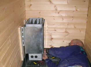
The specifics of connecting a stove for a sauna is not in the extreme complexity of the circuit diagram: the circuit is typical and is tied to a controller, which is part of the remote control, everything is assembled simply as a children's designer. The difficulty lies in the special conditions. Sauna and bathhouse in general is a room with a high degree of danger of electric shock. The main factors that create this hazard are high temperature and humidity.
Temperature and humidity are very harmful for the insulation of cables and wires, so connecting a furnace for a sauna has its own characteristics.
The control panel for the furnace is not installed inside the sauna, it is mounted on the wall immediately in front of the entrance, at room temperature. To connect the control panel in the distribution panel, reserve a circuit breaker with a rating corresponding to the current load consumed by the furnace. The circuit breaker must be differential with a leakage current rating of 30 mA, or after the circuit breaker in the line must be RCD.

There are no special requirements for the cable for connecting the control panel. The traditional five-core (for a three-phase network) or three-core (for a single-phase network) is suitable VVG-ng or NYM cable. The presence of a protective earth conductor (PE) is mandatory in view of the already mentioned increased danger. The method of laying the input cable is also selected according to the situation. In the most general case, ordinary ones are perfect plastic boxes (cable channels).
But to connect the furnace itself and the steam generator, a conventional cable in vinyl insulation will no longer be categorically suitable. Use either special cable with heat-resistant rubber insulation, which sometimes even comes with a furnace, or single-core heat-resistant wires RKGM required section. Moreover, to protect the wires, use a grounded metal hose or metal pipe.
Since heat-resistant wires have a higher cost, and installation in a metal hose or in pipes is technically complicated, a compromise is possible with an additional mounting junction box. The box is mounted on the wall at a distance of about a meter from the furnace, at a height of about half a meter from the floor. It is possible to lay VVG-ng or NYM hidden to the box to connect the steam generator and directly the heating elements of the furnace. And from the box in the metal hose or pipes, it is the heat-resistant wires that are mounted.

As for the sensor or sensors, for their connection, special heat-resistant cables are included in the furnace kit, which in no case can neither be increased, nor subjected to twisting and intermediate connections. The installation location of the sensors is strictly stipulated in the installation and operating instructions, and you must not deviate from these requirements. The most typical installation options are above the stove, above the sauna exit and above the shelves.
A few words can be added about wall penetrations, which are inevitable when the remote control and the furnace are located in different rooms. At the same time, it is necessary to remember that wall penetrations must comply with PUE standards: a mortgage tube made of non-combustible material is installed at the penetration site, which, after pulling the cable, is also sealed with non-combustible and non-fire-spreading material, for example, cement. Power cable lines and sensor connection lines must not pass through the wall together.
Alexander Molokov
See also at electro-en.tomathouse.com
:
