Categories: Sharing experience, Novice electricians, Electrician at home, Automata and RCD
Number of views: 296324
Comments on the article: 17
About electrical protection devices for "dummies": residual current device (RCD)
 Imagine the following - a washing machine is installed in your bathroom. Whatever the well-known brand, devices of any manufacturer are subject to breakdown, and, say, the most banal thing happens - the insulation on the power cord is damaged and the network potential appears on the machine body. And this is not even a breakdown, the car continues to work, but it is already becoming a source of increased danger. After all, if you touch both the car body and the water pipe at the same time, we will close the electric circuit through ourselves. And in most cases it will be fatal.
To avoid these terrible consequences, they were invented RCD - residual current circuit breakers.
RCD - This is a high-speed protective switch that responds to the differential current in the conductors supplying electricity to the protected electrical installation - this is the “official” definition. In a more understandable language, the device will disconnect the consumer from the mains if there is a leakage of current to the PE (ground) conductor.
Let's look at the principle of operation of the RCD. For greater clarity, the figure shows its "internal" circuit diagram:
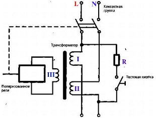
The main node of the RCD is differential current transformer. In another way, it is called a zero sequence current transformer. To make it easier for us and not to get confused in terms, we call this unit just a current transformer.
As can be seen from the figure, in this case it has three windings. The primary and secondary windings are included in the phase and neutral wires, respectively, and the third winding is connected to the starting element, which is performed on sensitive relays or electronic components.
Depending on thisdistinguish between electromechanical and electronic RCD.
The start-up device is connected with an executive control device, which includes a power contact group with a drive mechanism. The test button is used to check and monitor the health of the RCD. Now imagine that a load is connected to the output of our circuit. Naturally, a current will immediately appear in the circuit, which will flow through the windings I and II. To further consider the principle of operation of the RCD, we will move on to a more visual scheme:
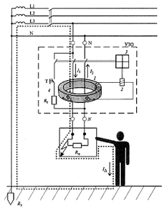
In normal mode, in the absence of leakage current, in the circuit along the conductors passing through the window of the magnetic circuit of the current transformer flows working current load. It is these conductors that form the primary and secondary windings of the current transformer counterclockwise connected. These currents will be equal in magnitude and opposite in direction: I1 = I2. They induce in the magnetic core of the current transformer equal, but counter-directed magnetic fluxes F1 and F2. It turns out that the resulting magnetic flux is equal to zero, the current in the third (executive) winding of the differential transformer is also equal to zero, and the starting element 2 is in this state at rest and the RCD operates in normal mode.
When a person touches open conductive parts or to the body of an electrical device to which an insulation breakdown has occurred on the phase (primary) winding of the current transformer, in addition to the load current I1, an additional current flows - leakage current (IΔ is indicated in the diagram), which is for a current transformer differential (differential: I1-I2 = IΔ).
It turns out that our currents are unequal, therefore, magnetic fluxes are also unequal, which no longer cancel each other out. Because of this, a current appears in the third winding.If this current exceeds the set value, then the starting element is triggered, acts on the actuator 3.
The actuator, consisting of a spring actuator, a trigger mechanism and a group of power contacts, opens the electrical circuit, as a result of which the unit is disconnected from the network. To carry out periodic monitoring of serviceability (operability) of the RCD, a test button 4 is provided. It is connected in series with the resistor. The resistor value is selected in such a way that the differential current is equal to the rated current of the residual current of the RCD trip (we will talk about the parameters of the RCD later). If the RCD is triggered by pressing this button, then it is working properly. Typically, this button is indicated by “TEST”.
Three phase residual current circuit breakers work approximately the same principle as single-phase. In three-phase RCDs, four wires pass through the core window - three phase and zero. Circuit diagram the simplest three-phase RCD is shown in the figure:
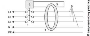
A three-phase RCD includes a circuit breaker 1, which is controlled by an element 2, which receives a trip signal from the secondary winding 3 of a current transformer 4, through the window of which there passes a neutral working wire N and phase wires L1, L2 and L3 (5).
If the load is equal in the zero and phase (or three phase) wires, their geometric sum is equal to zero (the current in the phase wire of a single-phase RCD flows in one direction, and the current in the neutral wire flows exactly the same value in the opposite direction). Therefore, there is no current in the secondary winding of the current transformer.
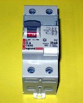
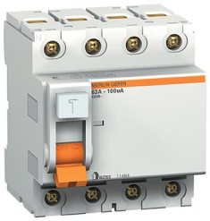
In case of current leakage to the grounded case of the power receiver, as well as when a person standing on the ground or on the conductive floor accidentally touches the phase wire of the electric network, the equality of currents in the primary winding of the current transformer will be violated, since the leakage current will pass along the phase wire, in addition to the load current, and a current will appear in its secondary winding - just like in the above description of the operation of a single-phase RCD. The current flowing in the secondary winding of the transformer acts on the control element 2, which, through the switch 1, disconnects the consumer from the mains. The appearance of a three-phase RCD is shown in the figure:
Let's consider practical schemes of inclusion of RCD in switchboards.
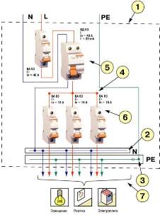
RCD switching circuit for single-phase input. Here we apply a switching circuit with a separate zero (N) and ground (PE) buses. As you can see in the figure, the RCD (5) is installed after the input circuit breaker, and after it circuit breakers are installed to protect and switch individual loops. Looking ahead, I want to note that the presence of an automatic - RCD connection is mandatory, since the RCD does not provide current protection, both thermal and short circuit. Instead of this “combination” - automatic - RCD, you can use one universal device. However, more on that later.
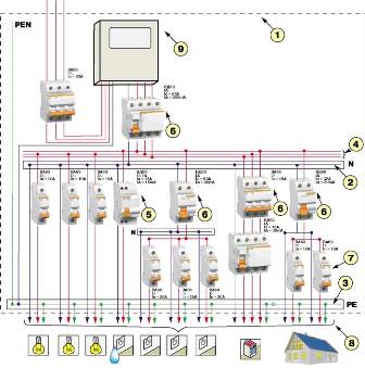
The circuit of the RCD with three-phase input. In contrast to the previous scheme, protection is provided for both single-phase and three-phase consumers. In addition, the combination of the input of zero and "ground" tires (PEN) is used. The electricity metering device - an electric meter - is connected between the input circuit breaker and the RCD. As you remember from the reviews on metering schemes, all switching devices that are installed before the metering device must be sealed with an energy supplying organization. Consequently, the design of the opening circuit breaker should allow for this.
Before that, we talked only about electromechanical RCDs. But if you remember, I mentioned that sometimes there are electronic devices. In principle, an electronic RCD is constructed in the same way as an electromechanical one.
Instead of a sensitive magnetoelectric element, a comparison device is used (for example, the most common example is a comparator).For such a circuit, you need your own built-in power supply - after all, you need to power the electronic circuit with something.
The differential current is very small, therefore, it must be amplified and converted to a voltage level, which is supplied to comparison device - comparator. All this, of course, reduces the overall reliability of the device, compared with the electromechanical one, here is just the case - the simpler the better. And to be honest, I have not come across certified electronic RCDs at all. Therefore, I cannot say something good or bad about them. Therefore, let us leave electronic UZO aside and dwell on one of the main points in considering electromechanical protective shutdown devices - their parameters:
RCDs have the following main parameters:
network type - single-phase (three-wire) or three-phase (five-wire)
rated voltage -220/230 - 380/400 V
rated load current - 16, 20, 25, 32, 40, 63, 80, 100 A
rated breaking differential current - 10, 30, 100, 300 mA
type of differential current - AC (alternating sinusoidal current that suddenly or slowly increases), A (like AC, additionally rectified ripple current), B (alternating and constant), S (delayed response time, selective), G (like selective, only the delay time is shorter).
I want to note one important point regarding the parameters of RCDs. Many are misled by the rated load current deposited on the device body, and it is taken for the same parameter as in the circuit breaker. However, this parameter in RCDs characterizes only its "current throughput capacity", maybe this expression is not quite correct, but I introduced it for the accessibility of the concept of "rated load current RCD".
The UZO load current cannot be limited and it is necessary to protect it from current overloads and short circuit currents by circuit breakers, which provide protection against current overload and short circuit currents. The load current of the RCD should be chosen so that it is one step (the rated current range) more than the rated current of the circuit breaker of the protected line. That is, if there is a load protected by a circuit breaker for a current of 16 Amps, then the RCD should be selected for a load current of 25 Amps.
This raises a logical question - why not combine a circuit breaker and an RCD in one case, especially when the RCD is used to protect only one power loop? Indeed, in this case, they still work "in tandem." This point was touched on a bit in the previous article. Well, the question is quite logical and such devices, of course, exist. They are called differential circuit breakers or just diffavtomats.
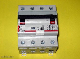
In the figure you just see such a device. This is a three-phase differential circuit breaker. As in the three-phase RCD, it has four clamps - phase and zero, and a TEST button. If it dwells on its internal structure, then something new is difficult to say here. This is a circuit breaker and RCD in one bottle.
The cost of diffavomats is quite high. For example, three-phase models of well-known foreign manufacturers have a cost of about 100 Euro. Relatively expensive pleasure. However, a bunch of AB + RCDs will have a roughly comparable cost, and instead of four standard 17.5 mm modules on a DIN rail (with a three-phase version), it will take eight. So in some cases, diffavomats are still preferable, especially if there is a problem of free space in the distribution panel.
How to check the performance of an RCD or a differential automat? We already mentioned the TEST button. However, such a check is very superficial and does not always reflect the real essence of things. Therefore, for objective verification, test circuits or specialized devices are used.
Mikhail Tikhonchuk
See also at electro-en.tomathouse.com
:

