Categories: Practical Electronics, Repair of household appliances, How does it work
Number of views: 47109
Comments on the article: 0
DIY remote control repair. Part 1. Development History and Remote Control Device
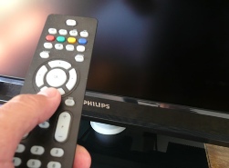 Remember how in the cartoon “three from Prostokvashino”, Uncle Fedor’s mother said: “I’m so tired at work that I can’t even watch TV!” Apparently, this phrase is the answer to the question why all modern household equipment has infrared remote controls. But, if you look, it all started much earlier.
Remote control with wires
The first work on remote control was carried out by the Germans in the late 30s of the twentieth century, even before the outbreak of World War II. The object of automation was a tube receiver. The control panel was a separate metal panel with buttons. Pressing the button triggered the actuator, - relay, electromagnet or motor. The connection between such a remote control and the receiver was made by a multicore cable, which still tied the listener to a specific place.
Similar remotes were in the Soviet first-class tube TVs. It was a small plastic box with a volume control, connected to the TV with a wire. Besides the volume, such a remote control could not control anything. But such a remote control undoubtedly created certain conveniences. After all, then there was no annoying advertising and the film had to be watched from beginning to end.
Ultrasonic Remote Control
The first wireless remote control owes its birth to the American Hasso Plattner. In 1972, after leaving IBM, he organized his own company and often went around the world to establish business contacts and ties. An embarrassing incident occurred at a meeting with JVC management.
When discussing a problem, Plattner got up and moved to the TV to show some detail on the screen with his finger. But he didn’t get to the screen, tripping over the remote control cable. He poured a cocktail on a suit and said in his hearts: “Couldn’t it be possible to switch channels on the radio wave?”, Which drove the Japanese companions into the paint. And exactly one year later, the first ultrasound remote control appeared.
The principle of its action was to feed its frequency by pressing each button. Ultrasound was captured by a microphone and amplified by an amplifier, which used several parallel channels with resonant circuits. At the outputs of these channels appeared control voltage. With this method of channel coding, not much was obtained.
Further development of electronics, in particular the appearance of INTEL microcircuits, made it possible to abandon such multi-frequency encoding. At one ultrasonic frequency, due to various modulation methods, it became possible to transmit much more commands than with multi-frequency coding. One of the first devices equipped with an ultrasonic remote control was a TV company RCA. The coding of commands was carried out using pulse width modulation (PWM).
These remotes had a number of disadvantages. First of all, large dimensions and power consumption. This was due to the fact that ultrasonic radiation is readily absorbed by household items - clothing, upholstered furniture, carpets. Therefore, the radiation power needed to be increased, which reduced the battery life.
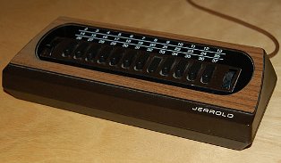
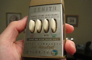
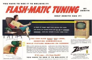
Fig. 1. The first remote controls
Specialized Remote Control ICs
Things got better after INTEL developed its first 8080 microprocessor. GRUNDIG and MAGNAVOX, who made the first specialized microprocessor, took this new development. In this case, the processor generates the desired digital command code under the influence of the pressed button.Thus, a specialized microcircuit for a remote control is nothing but microcontroller with an already flashed program. Such remote controls were called TELEPILOT.
IR remote control
The first color TV with microprocessor control and remote control (RC) on IR rays was released jointly by GRUNDIG and MAGNAVOX in 1974. Already in this model, the switching channel number (OSD system) was shown in the corner of the screen. This command system is called ITT. It was the firstborn of the company GRUNDIG.
Subsequently, PHILIPS, which developed the RC-5 command system, took up research in the field of remote control. The new system allowed to encode 2048 commands, which is 4 times the number of teams in the ITT system. The carrier frequency was chosen to 36KHz, which did not interfere with European broadcasting stations and the operation of remotes with ultrasonic transmitters with a frequency of 30 and 40KHz, and also provided a sufficient reception range.
But the electronic equipment did not stand still, but as one movie hero used to say, he went forward with leaps and bounds. Televisions improved, VCRs and stereo systems appeared, satellite tuners, CD and DVD players and much more.
To control the new technology, new remote controls were also required, and accordingly, new microcircuits had to be developed. Such microcircuits were developed by SIEMENS and THOMSON. The carrier frequency of the new remote control was also 36KHz, but another method of signal modulation was used - two-phase modulation. With this modulation, the carrier frequency was more stable, which provided increased range, increased noise immunity and reliability.
PHILIPS again made a further contribution to the development of remote control systems. At the beginning of the 90s of the last century, she combined all the best that was in the RC-5 and SIEMENS systems. The resulting product is called the “Unified Command System”. Its essence is as follows. The remote control of such a system has the functions “MENU 1” and “MENU 2”. In each of these functions, the same button executes different commands, and it turns out that fewer buttons can execute more commands.
Subsequently, control panels penetrated many other areas of household appliances. IR radiation is currently controlled by air conditioners, fans, wall-mounted fan heaters, chandeliers and sockets. Even some models of car radios and digital cameras have a remote control.
With all the variety of remotes and devices controlled by them, they all work almost the same: the infrared LED of the remote control, when pressed, emits packets of infrared pulses (flashes) that are received by the photodetector (“eye”) of the TV or other device. The modern integrated photodetector is a rather complicated device, although its appearance does not say so. The appearance of the photodetector is shown in Figure 2.
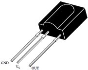
Figure 2. Photodetector
The receiver is configured to receive pulses with a carrier frequency of 36KHz, which corresponds to the RC-5 protocol. If near the photodetector it is easy to turn on, for example, a battery, an IR LED, then its steady light on the "eye" will not have any effect, even if this LED is brought close to the photodetector. Also does not affect daylight and artificial light. Such selectivity is due to the fact that there is a bandpass filter in the amplification circuit of the photodetector signal. The block diagram of the photodetector is shown in Figure 3.
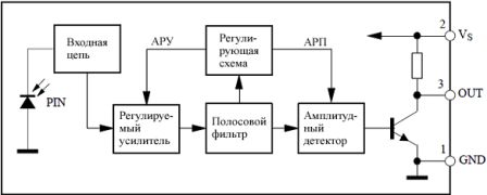
Figure 3. Block diagram of a photodetector
The RC-5 protocol will not be explained in detail here, since this ignorance will not affect the further story, and actually the repair of the remote control. Those who want to get acquainted with the RC-5 protocol can find a more detailed description of it on the Internet. This is a topic for a separate article.
Remote control device
With all the variety of modern remote controls, all models are arranged almost identically. The main difference is most often in appearance, in the design of the device.As mentioned in the first part of the article, the basis of modern remote control is a specialized microcontroller. The program in MK is recorded during the manufacturing process at the plant and cannot be changed in the future. When included in the circuit for such an MK, a minimum number of attachments is required. The scheme of the modern remote control is shown in Figure 4.
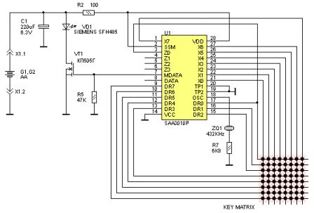
Figure 4. Diagram of a modern remote control
The basis of the entire device is a U1 chip type SAA3010P. Although the letters may be different, which speaks of another company producing the chip. But the numbers still remain 3010.
As mentioned above, there are practically no hinged parts. First of all, this ceramic resonator, often referred to as quartzalthough this is not entirely accurate. Its purpose is to synchronize the internal oscillator of the microcircuit, which provides the required time characteristics of the output signal.
The matrix of keys (KEY MATRIX) is shown in the lower right corner of the diagram. Its rows are connected to the terminals DR0 ... DR7, and the columns, respectively, to the terminals X0 ... X7. When you click on any button, one pair is closed - a row, and an impulse sequence corresponding to the pressed button appears at the output of the microcircuit. Each button gives its own sequence and no other! In total, it is possible to connect 8 * 8 = 64 buttons, although in practice it may be less.
The output signal in the form of voltage pulses is supplied to the gate of the field effect transistor VT1, which in turn controls the operation of the IR LED VD1. The control algorithm in this case is very simple: the transistor opens - the LED lights up, the transistor is closed, - the LED goes out. In this case, they say that the transistor is in key mode. As a result of such flashes, pulse packets corresponding to the RC-5 control protocol are formed.
The power supply of the circuit is made from two galvanic cells of type AA, whose energy is enough for at least a year. In parallel with the batteries, there is an electrolytic capacitor C1, which by shunting the internal resistance of the batteries, extends their service life and ensures the normal operation of the remote control with a few “dead” batteries. The LED in pulsed mode can consume current up to 1A.
After considering the remote control circuitry, it seems that we can say that there is absolutely nothing to break with such a simple device, but this is not so. It is the remote control that most often causes trouble to the owner of the TV. How to repair the remote control, what are its main "diseases", as well as how and how to cure them will be described in the second part of the article.
Continuation of the article: DIY remote control repair.
Boris Aladyshkin
See also at electro-en.tomathouse.com
:
