Categories: Featured Articles » Home automation
Number of views: 85680
Comments on the article: 11
Motion Sensor Connection Diagrams
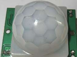 Motion sensors are devices that respond to moving, rather than stationary, objects. In this they differ from the presence sensors configured to operate upon disappearance, disappearance of moving objects in the controlled area.
In other words, the device that controls the movement should work when a person is inside the observed space, when he moves or froze, but at least just moves his fingers. At the same time, presence control devices are triggered when people have completely left the room or there is a completely frozen person left in it who does not make any movements.
Both groups of these sensors can work based on:
-
capture of sound vibrations by sensitive acoustic systems;
-
the perception of thermal radiation caused by the human body by infrared receiverspassive action;
-
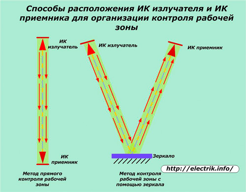
overlapping infrared invisible to the human eye directed from the emitter to the receiveractive method.
There are still other ways to detect a moving person, but they, like the acoustic method, are rarely used. And in home appliances, motion sensors that work with electromagnetic waves located in the infrared spectrum are most often used. They are described in this article.
IR sensor receivers have a general operating principle.
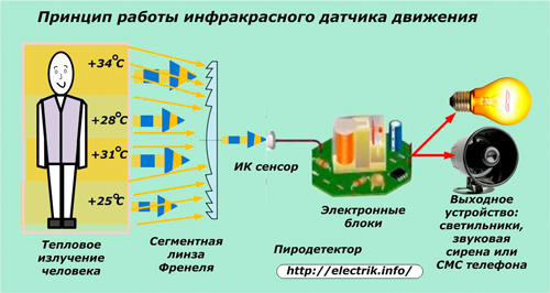
Motion sensors and presence sensors pick up infrared radiation distributed in all directions from any objects located in the field of view. Thermal rays, as in a conventional optical system, for example, a camera, fall on a segmented lens that works according to the Fresnel principle.
This glass or optical plastic construction is created with a large number of concentric sectors / segments, each of which forms a narrow beam of parallel heat rays to the IR sensor.
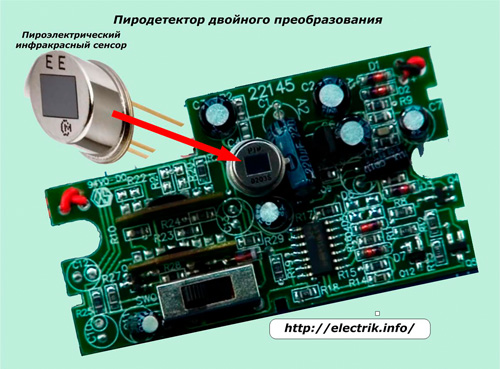
It is also called the term “PIR sensor” because it has a pyroelectric effect - it creates an electric field proportional to the received heat flux. The signal received by him is processed by electronic devices.
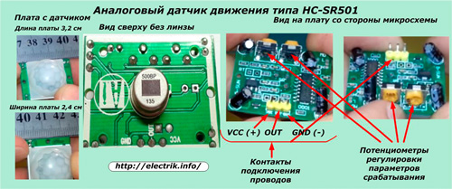
In most sensor designs, the pyrodetector works with analog values. An example is HC-SR501 Series Motion Sensor.
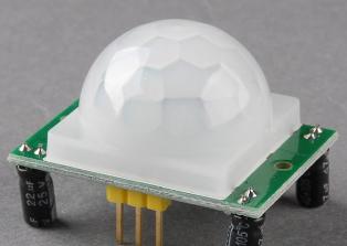
It has small dimensions, works on the basis of a microcircuit, has three terminals for connecting power and load wires, two adjusting potentiometers. When triggered, it generates a control electric signal with a voltage of 3.3 volts and a current of several milliamps.
Recently, units have been introduced that implement double conversion and processing of commands based on digital signals.
This allows the use of microprocessor devices and computer technology for further signal transformations and the formation of various control algorithms for automatic devices.
Both analog electronic and digital sensors are connected to power supplies and have output devices that switch the load in the primary network.
One of the principles is laid in the electronics operation algorithm:
-
motion detection;
-
response by stay.
When a person appears in the sensor’s field of action, by his presence he makes changes to the heat balance of the environment, and all his movements are recorded through the Fresnel lens as a camera lens. The electronic units operate and issue an electrical signal to the control contact.
This ends the functions of the sensor itself, although the switching process of the actuators has not yet been completed, and the power of the control signal of the motion sensor for switching lighting fixtures, turning on the sound siren, sending SMS to a mobile phone or performing other tasks is not enough.
This signal must be amplified and transmitted to a powerful contact to switch the load.
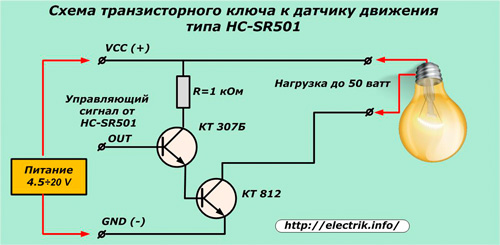
The HC-SR501 motion sensor discussed above cannot perform these functions on its own. To implement them, you can assemble a simple transistor switch on bipolar transistors.
Power = 4.5 ÷ 20 volts from an additional source is supplied to the VCC and GND terminals of the motion sensor and key, and the control signal from the OUT terminal of the sensor is supplied to the amplifier terminal of the same name. A load of the appropriate voltage is connected to the output circuit.
If you use this scheme to turn on the mobile phone, you can receive SMS on your mobile phone, which will be a signal about the appearance of unexpected guests in the security zone.
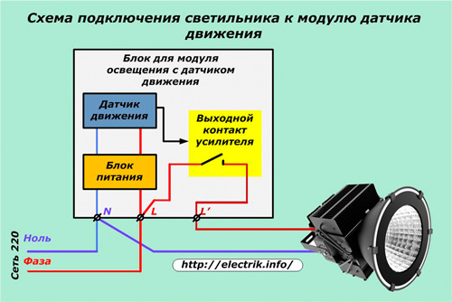
Most ready-made modules for lighting circuits with motion sensors have a built-in amplifier and a power contact switching the load circuit. The designs of such units, powered by a 220 V network, have three terminals for connecting wires directly on the housing, two of which supply power (phase L and zero N) and the third L ', together with zero N, is used for switching luminaires.
Active motion sensors
Devices working on the principle of monitoring the channel between the IR emitter and the receiver have approximately the same algorithm, are tuned to a common frequency, like the remote control of a TV or a wireless computer mouse with their receivers. They can have autonomous power independent of a stationary electric network.
In this case, one of the layout schemes of the modules of the direct or rotary method of forming the path using mirrors is performed.
Sensor Connection Diagrams
Simple wiring diagram shown in the picture.
With this connection, the lamp operation mode is fully consistent with the algorithm laid down by the electronic circuit and is adjusted by adjustment potentiometers.
On simple sensor designs, two controllers are installed:
1. LUX - the level of illumination, upon reaching which the sensor is triggered (for example, there is no need to use electric light in sunny weather). For regulation, its highest value is initially set;
2. TIME - the duration of the timer or, in other words, the length of time in which the lamp will light after detecting movement. Usually set the minimum value, because with each new movement, the sensor will constantly restart.
Usually these two adjustment parameters are enough to configure the control of household fixtures. At sophisticated security motion sensors there are two more potentiometers:
1. SENS - sensitivity or range. It is used to reduce the control zone in those cases when it is not possible to limit it to changing the orientation of the motion sensor;
2. MIC - acoustic noise level of the built-in microphone at which the sensor is triggered. But in domestic conditions this function is not needed - the sensor will be triggered by extraneous sounds of passing cars, children's exclamations ...
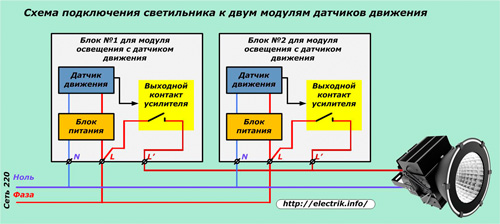
Connection scheme of the lamp to two sensors
This method is used in places where it becomes necessary to control lighting from two remote points with a limited view for one sensor.
The device terminals of the same name are connected in parallel to each other and are output to the power supply network and the lighting device. When the output contact of any sensor is activated, the lamp lights up.
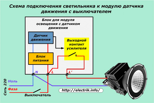
Connection diagram via switch
This method is used when a motion sensor block is added to an existing lamp with a switch. When the switch is turned on, the circuit fully works as it is configured by the electronics. And when the contact is open, the phase is removed from the power supply and the motion sensor is taken out of operation.
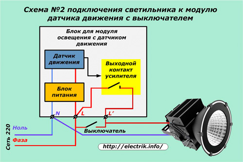
Practice has shown that among apartment owners, when leaving the premises, the habit of automatically turning off the light with a switch remained. After that, when entering a person’s room, the motion sensor is put out of operation. To exclude such situations, the contacts of the switch are shunted, by which the transition to the previous circuit is carried out.
In this circuit, the on switch completely bypasses the output contact of the motion sensor. It is used when a person has been in a stationary position for a long time, and the shutter speed is small and you have to make extra distracting movements to turn on the lamp.
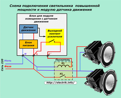
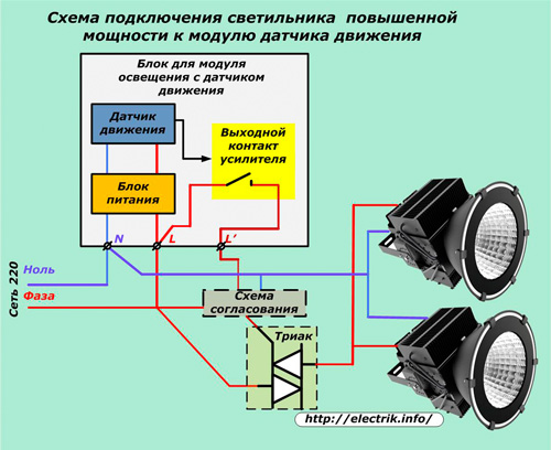
Wiring diagram for powerful loads with electromagnetic devices
A motion sensor unit with low power contacts can be used to light control very powerful lighting fixtures. For this, an intermediate device is used - magnetic switch, relay or contactor of the corresponding rating. Its winding is connected to a low-power sensor contact, and the power contact commutes the load of the lighting system.
In this scheme, as in all others, it is necessary to accurately calculate the switched capacities and select power contacts for them. After inclusion in the work, the currents of the loads are necessarily measured and compared once again with the power of the contacts. For reliable long-term operation of the system, it is necessary to create a margin of power.
A similar circuit with electromagnetic devices is capable of long and reliable operation. But, she has two significant drawbacks:
1. increased noise and electromagnetic interference that accompanies the process of moving the armature during switching;
2. the constant wear of the contact system due to discharges arising from an open circuit, which requires periodic preventive maintenance.
Triacs and triacs are deprived of these shortcomings.
Connection diagram for powerful loads with semiconductor devices
In this case, there are no all kinds of noise and interference. But for the semiconductor device to work, it is necessary to convert the control signal of the motion sensor into a harmonic that coincides in frequency with the mains voltage. To do this, a special matching circuit is created that provides alternating current to triac control electrode.
When the matching circuit is operating, the triac is open. and the lights are on. When there is no control signal, the triac is closed, and the lighting it controls is turned off.
The disadvantage of this circuit is the design complexity of the matching signal of the electronic device.
The choice of installation location and method of orientation of the sensors
Depending on its design, the motion sensor may have a different viewing angle for monitoring space from a few degrees to a circular view, which is usually used with ceiling mounts.
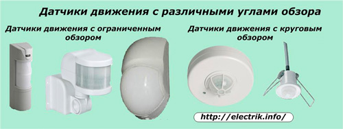
These angles are distributed in horizontal and vertical planes, determine the observation area, are indicated in the documentation.
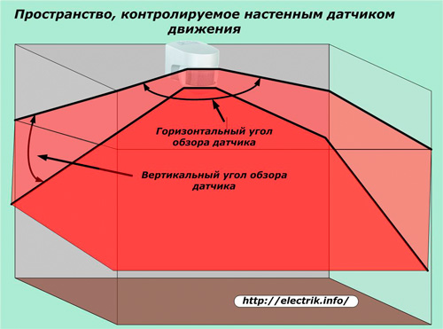
Sensors designed for wall mounting usually have an overview of the order of 110 ÷ 120 or 180 degrees horizontally and 15 ÷ 20 - vertically.
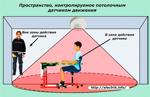
Outside this space, no movements are detected by the sensors. Therefore, when installing a motion sensor, it is important not only to select them according to the characteristics of the review, but also to adjust after installation to adjust the direction. Designs with a movable viewing body make commissioning easier, and for other devices it is necessary to carefully think through and perform the initial installation.
Ceiling Sensors Usually Have 360 Visionabout horizontally, which is distributed cone from top to bottom.Its control zone is much larger, but it can also have an inconspicuous space in the corners of the premises.
Impact of foreign objects on the operation of sensors
When installing and configuring the motion sensor, it is important to take into account the conditions of their placement, to assess the impact on their reliability of nearby objects and various energy sources. Thermal heaters, swaying tree branches, cars passing by, elevator cabs and other objects can cause frequent false positives.
When there is no way to get rid of them, then the sensitivity of the device is roughened with a potentiometer or the interference zone is shielded.
Read also:How to choose, configure and connect a photo relay for outdoor or indoor lighting andWiring diagrams in an apartment and a house - the best articles
See also at electro-en.tomathouse.com
:

